In the first six months of developing Closer's sensing architecture, we operated with two layers: ultrasonic proximity sensors arranged in a ring around the robot chassis, and a forward-facing depth camera for spatial geometry. Both worked well for their intended purposes. The ultrasonics gave us 360-degree presence detection at ranges useful for speed reduction decisions. The depth camera gave us point-cloud obstacle geometry in the forward travel direction.
Then we put the prototype in a real warehouse aisle for a two-day test session, and started collecting the edge case log.
The gap that neither sensor handles well
Depth cameras have a minimum effective range. Below roughly 200mm from the lens, structured-light and time-of-flight depth cameras either produce no valid depth data or produce data with accuracy too low to use for proximity decisions. The lens optics and the geometry of the light pattern or pulse create an area directly in front of and beneath the camera mounting position that is effectively blind at close range.
Ultrasonic transducers have a different version of the same problem. The transducer's beam angle is typically 10 to 15 degrees off the pointing axis, and the transducer has a minimum blanking distance where transmitted and reflected pulses overlap and cannot be cleanly separated. At distances below 80 to 150mm (depending on the transducer specification), the return signal is unreliable. Objects within that range may not register as proximity events.
Both sensors also have a floor-profile limitation: their detection geometry favors objects that project above the floor at the sensor's mounting height. A large flat object lying on the floor -- a shipping bag, a dropped piece of cardboard, a cloth -- may partially or fully evade detection because its reflective surface is oriented horizontally rather than at an angle that produces a useful return signal for either sensor type.
During our Fukuoka test sessions, we logged three categories of near-miss events that involved floor-level or low-profile objects. One involved a flat cardboard sheet at the end of an aisle. One involved a soft goods shipping bag that had fallen from a shelf and was partially flattened on the floor. One involved a small step-stool that had been left in a cross-aisle, whose feet sat in the transducer shadow zone of our forward ultrasonics.
None of these objects caused contact with the robot body during the test sessions -- we had manual safety operators running shadow-mode on every test run. But the sensor logs showed that the proximity response was either absent or delayed past our acceptable threshold for all three events.
The decision to add a third sensing layer
Adding floor-contact force sensing was not in the original system architecture. We added it after the test session data made the gap clear enough that we could not proceed to unmonitored operation without addressing it.
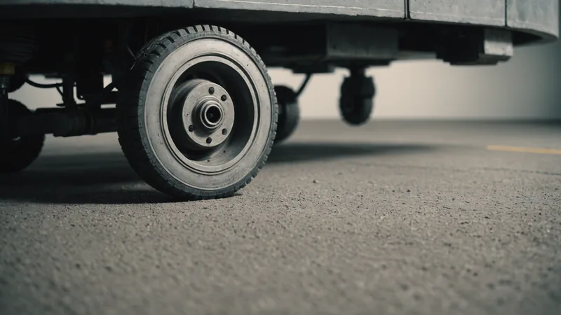
Floor-contact force sensing in our current implementation uses strain gauges integrated into the wheel suspension mounts at each of the four drive wheels. Each wheel assembly measures vertical and lateral force through its suspension travel. The sensing is passive and continuous: it does not require active polling or trigger-based measurement, and it has no minimum range limitation because it measures physical contact with the floor and with objects the wheels encounter.
When a wheel contacts an unexpected surface height change -- an object on the floor, a protruding pallet foot, an uneven surface transition -- the force signature differs measurably from normal floor traverse. Our contact detection algorithm runs on the wheel controller at 200Hz and classifies force signatures into three categories: normal floor traverse, surface irregularity (a floor surface variation that does not require a stop), and contact event (a force profile that requires an immediate stop and fault log).
The contact event threshold was calibrated against two scenarios: an object with 20mm or more of floor clearance projection (the step-stool scenario), and a low-profile soft obstacle with less than 10mm projection (the shipping bag scenario). Both trigger a contact event at our current threshold settings. The calibration took several days of test runs with known objects at known floor positions, with the sensor logs compared against ground-truth position data.
What the third layer catches that the first two miss
Concrete cases where floor-contact sensing detects what the camera and ultrasonics did not, in our test and pilot data:
Low-profile objects under approximately 100mm height are the primary category. Below this height, the ultrasonic ring mounting position (160mm above the floor on our current chassis) creates a detection shadow. The depth camera, mounted at 420mm above floor level, also has reduced sensitivity to objects in the 0 to 100mm height range because those objects appear at the very bottom of the camera's field of view with low point density from the structured light pattern.
Objects with non-reflective or horizontally-oriented surfaces. The depth camera requires a surface to return sufficient light to register a depth measurement. A dark-colored cloth bag lying flat on the floor may not produce a sufficient return in warehouse lighting conditions. Ultrasonic return from a horizontally-flat soft surface is also degraded. The floor-contact layer makes no optical or acoustic assumption about the object -- it measures the force of contact directly.
Obstacles inside the near-field blind zone of the forward-facing sensors. The 80mm transducer blanking distance and the camera minimum range create a region immediately in front of the robot where neither sensor reliably detects. If an object is sitting in that zone as the robot approaches at slow speed (less than 0.3 m/s, approaching from a stopped state), the floor-contact layer will detect wheel contact before the robot body contacts the object.
Integration into the safety response pipeline
The floor-contact layer is not a primary proximity sensor. It is a last-resort contact detection system. The intended sequence is: ultrasonic ring detects proximity and triggers speed reduction at 700mm clearance, depth camera confirms geometry and guides deceleration curve, robot stops before reaching contact range. The floor-contact layer should never trigger in normal operation if the first two layers function correctly.
When the floor-contact layer does trigger a contact event, it goes to the safety controller as a fault requiring a full stop and maintenance review. It does not trigger a deference wait (as proximity events do) because contact has already occurred. The stop is immediate, the fault is logged with full sensor state, and the robot does not resume autonomous operation until the fault is cleared by an operator.
We track the rate at which floor-contact events occur across pilot deployments as a quality indicator for the first two sensing layers. A contact event rate above approximately one per 100 operating hours suggests that the first and second layers are not catching something they should be catching in that specific environment. In our current pilots, the contact event rate is below that threshold, which tells us the three-layer architecture is functioning as intended: the third layer exists for edge cases and is actually encountering edge cases at the expected low frequency rather than becoming a primary detection path.
Tradeoffs and limitations
Force sensing at the wheel assembly is sensitive to floor surface variations that are not obstacle contacts. Expansion joints, slight floor level transitions at door thresholds, and surface texture transitions between tile and concrete can produce force signatures that the classifier needs to distinguish from contact events. Tuning the surface irregularity versus contact event boundary took the most time in the calibration process, and it remains the area where the most false classification events occur in new environments.
We do not claim the three-layer architecture solves all floor-level obstacle detection problems. A wide shallow obstacle lying flat across the full robot path width, extending beyond the wheel track width, would be detected by wheel contact rather than being detected in advance -- because neither the ultrasonic ring nor the depth camera has reliable detection for such a scenario. In that case the floor-contact layer catches the contact but cannot prevent it. That is an unsolved edge case we document in our test scenario library and review with operators during site assessment before deployment.